(LE Coded 1M) Bidding Farewell to the "Metal Shielding Effect": MN54L's Penetration Power Ensures IIoT Device Connection Stability in Containers and Cabinets
[TAIWAN, 27th November 2025]

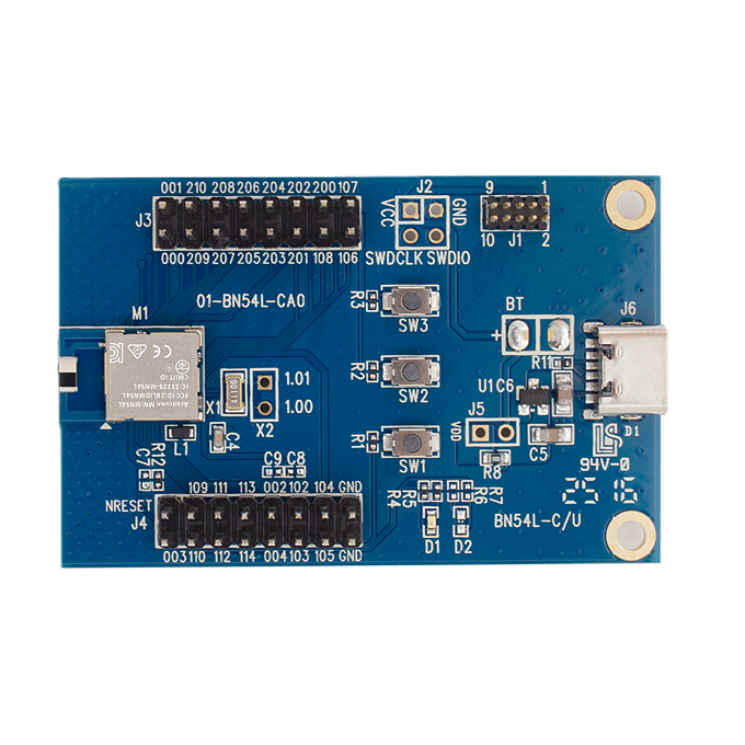
[Quick Validation] Arad MN54L Module Bluetooth Container Signal Penetration Bidirectional Communication Test Report (1M PHY)
Introduction
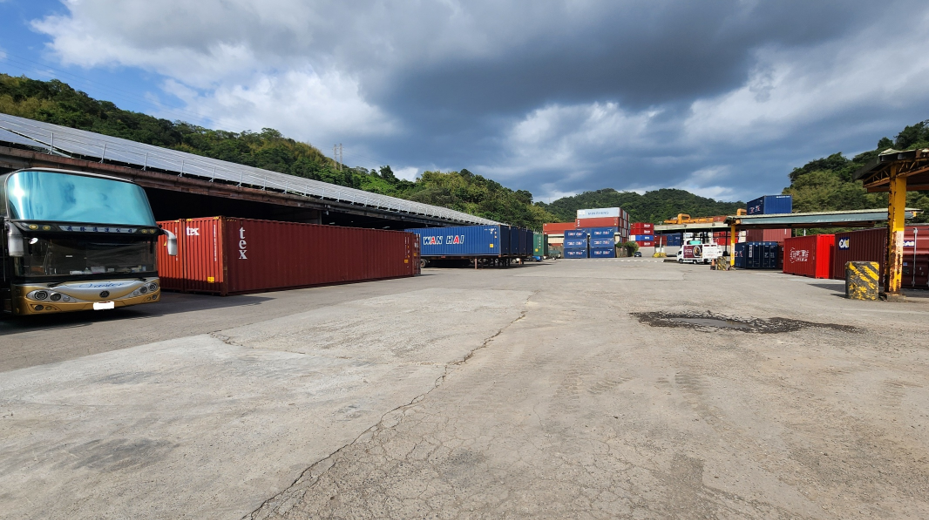
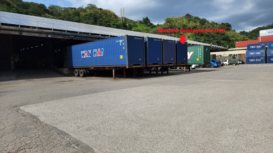
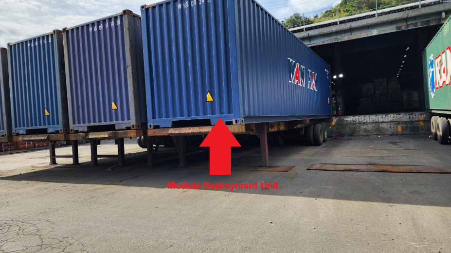
This test aims to validate the signal penetration and connection capabilities of the MN54L-C15 Bluetooth module in an extreme Radio Frequency (RF) shielding environment. By installing the Device Under Test (DUT) inside the furthest end of a large metal shipping container and conducting connection tests within a parallel-container setting, we simulated severe conditions common in Industrial IoT (IIoT) applications where signals must penetrate metal structures, such as equipment cabinets, walls, or buildings.
1. Test Objectives
✅ Quickly verify the maximum effective communication range of the MN54L BLE module when communicating with external devices from inside a large metal container.
✅ Test the communication performance of the Chip Antenna version module at its optimal axial direction while penetrating the container.
2. Test Date & Environment
|
Item |
Details |
|
Test Date |
November 26, 2025 |
|
Test Environment |
Outdoor environment utilizing a standard 40-foot shipping container. |
3. Equipment Required
|
Category |
Device |
Details |
|
SLAVE/PERIPHERAL |
Emitting Board (DUT) |
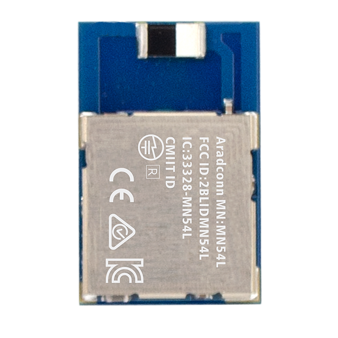
MN54L-C15 Test Module |
|
MASTER/CENTRAL 1 |
MN52H-U40 |
Tx Power: +8 dBm |
|
MASTER/CENTRAL 2 |
iPhone 7 |
Tx Power: 0 dBm |
|
Test Software |
LightBlue®; Aradconn custom BLE firmware. |
|
|
Measurement Tools |
Google Maps, Mobile GPS Positioning. |
4. Test Parameters
|
Parameter |
Description |
|
TX Power |
+8 dBm (Set on MN54L and MN52H-U40) |
|
PHY Mode |
1M (Standard BLE) |
|
Packet Size |
20 bytes |
|
Direction |
Line-of-sight (LOS) path was maintained for distance, but the signal path was Non-Line-of-Sight (NLOS) due to the container barrier. |
|
Antenna Position |
Inside the furthest end of the 40-foot container. |
|
Transmission Mode |
Connected mode (Verifying valid packet transmission). |
|
Environmental |
Temperature: 20°C, Humidity: 66% |
5. Test Procedure - MN52H-U40 (Master, +8 dBm)
5.1 Preparation and Connection Establishment
1. Equipment Setup: Confirmed that the SLAVE/PERIPHERAL (MN54L-C15) and the MASTER/CENTRAL (MN52H-U40) TX Power were both set to +8 dBm.
2. Transmission Rate: Set to 1M mode with 4 packets transmitted per second.
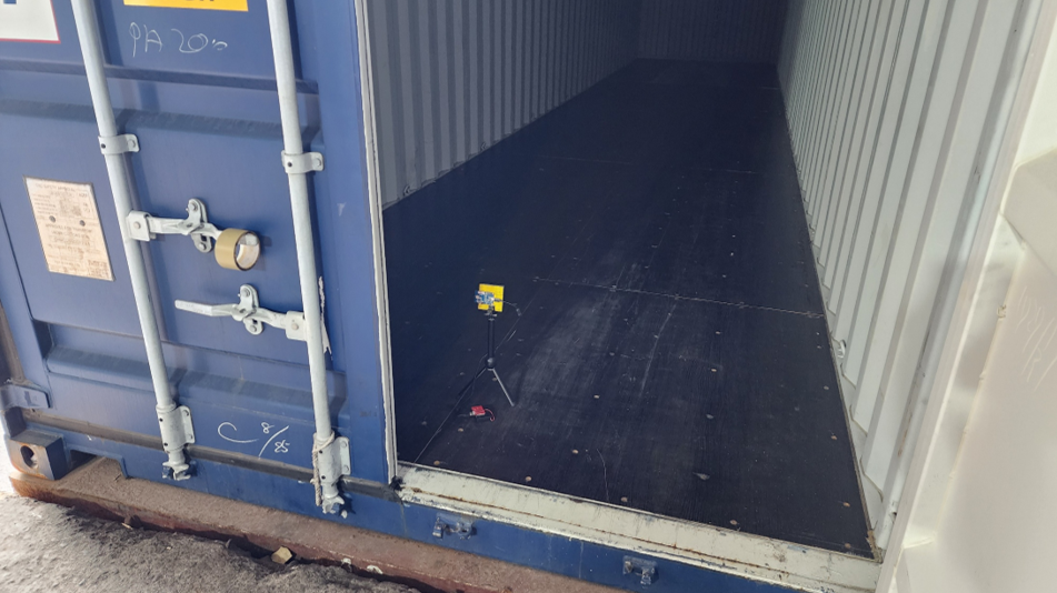
3. Starting Point: The SLAVE device was placed inside the furthest end of the 40-foot container, the container door was closed, and the antenna was oriented towards the MASTER's driver position.
4. Connection Check: The MASTER established an active connection and performed bidirectional packet transmission. Packet reception was verified via LED indicator lights on the module.
5.2 Distance Measurement and Data Logging
1. Incremental Test: The MASTER moved outwards along the LOS path in 10-meter increments (approx. 10 steps).
2. Monitoring: At each point, the connection status was monitored. Packet loss was identified by the LED indicators extinguishing or blinking irregularly. Continuous transmission/reception defined a valid connection.
3. Angle Test: At the distance where signal attenuation began, the impact of the SLAVE device's antenna rotation on the Packet Success Rate (PSR) was tested to confirm the signal pattern.
4. Maximum Range: Movement continued until significant packet loss occurred (e.g., LED blinking slowed down or stopped). Google Map and GPS were used to precisely record the disconnection distance and surrounding environment.
6. Test Procedure - iPhone 7 (Master, 0 dBm)
6.1 Preparation and Connection Establishment
1. Equipment Setup: Established an active connection between the iPhone 7 and the SLAVE, verifying packet reception via the LightBlue® interface.
2. Transmission Rate: Set to 1M mode with 4 packets transmitted per second.
3. Starting Point: The SLAVE device was placed inside the furthest end of the 40-foot container and the door was closed.
4. Connection Check: Connection status was monitored via the LightBlue® screen.
6.2 Distance Measurement and Data Logging
1. Incremental Test: The MASTER (iPhone 7) moved outwards along the LOS path in 10-meter increments.
2. Monitoring: At each point, connection quality was checked via the LightBlue® screen.
3. Maximum Range: Followed the same procedure as Section 5.2 (Step 4) to determine and log the maximum effective connection distance.
7. Test Results (Maximum Effective Connection Distance)
The table below shows the maximum distance at which the MN54L-C15 (PERIPHERAL) maintained a stable bidirectional connection after penetrating the container barrier:
|
MASTER (CENTRAL) Device |
Maximum Effective Connection Range (Meters) |
|
MN52H-U40 Bluetooth Module |
81.14 m |
|
iPhone 7 Mobile Phone |
59.87 m |
-
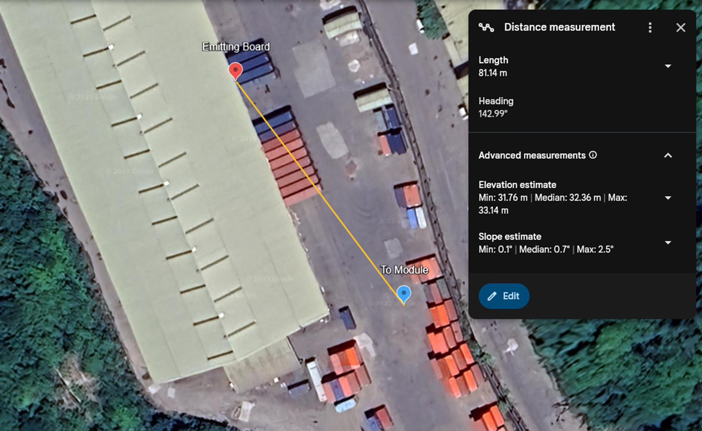
Note: The aerial view is not a photo of the actual site.
-
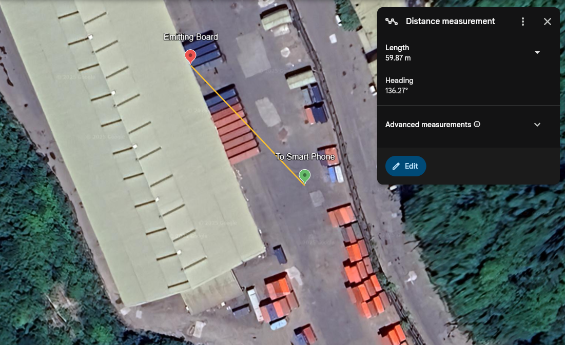
Note: The aerial view is not a photo of the actual site.
8. Test Conclusions and Observations
- Severe Signal Constraint: Compared to open-field test results, the connection range in the 1M mode dropped drastically from hundreds of meters to tens of meters. This confirms the extreme attenuation effect of the multiple metal containers on the 2.4 GHz Bluetooth signal.
- Pro-Grade vs. Consumer-Grade Performance Difference:
- MN54L (PERIPHERAL) paired with MN52H-U40 (MASTER) achieved 81.14m.
- MN54L (PERIPHERAL) paired with iPhone 7 (MASTER) achieved 59.87m.
- This result highlights that the professional-grade MN52H-U40 module, with its higher Tx power and superior receiver sensitivity, provided approximately 36% better connection performance when overcoming severe signal fading compared to the consumer-grade phone.
Conclusion: Despite the highly challenging RF environment, the MN54L-C15 module successfully penetrated multiple metal containers and maintained a stable connection, especially when paired with a professional Bluetooth MASTER module. This demonstrates that the MN54L possesses an adequate Link Budget and stable RF performance to meet the demands of industrial applications requiring communication through metal enclosures and multi-barrier scenarios.
-
 PERIPHERAL MODULE LOCATED
 -
 PERIPHERAL MODULE LOCATED
Image and Text Copyright Statement:
All text and image content in this article (including but not limited to headings, body text, analysis, and summaries) are the copyright of Arad Connectivity Co., Ltd. Any form of reproduction, reprinting, modification, or commercial use without written authorization is strictly prohibited.
📢 Get Ready for Our Latest Episode of BLE Tech Pulse Decoded on Aradtube!
We're diving deeper into this fascinating topic! Subscribe to our channel and hit that notification bell so you don't miss our latest video releases.
🔗 YouTube: https://www.youtube.com/@Aradconn
Edited by Intl. Commercial Development Manager: Mr. Tim Chien