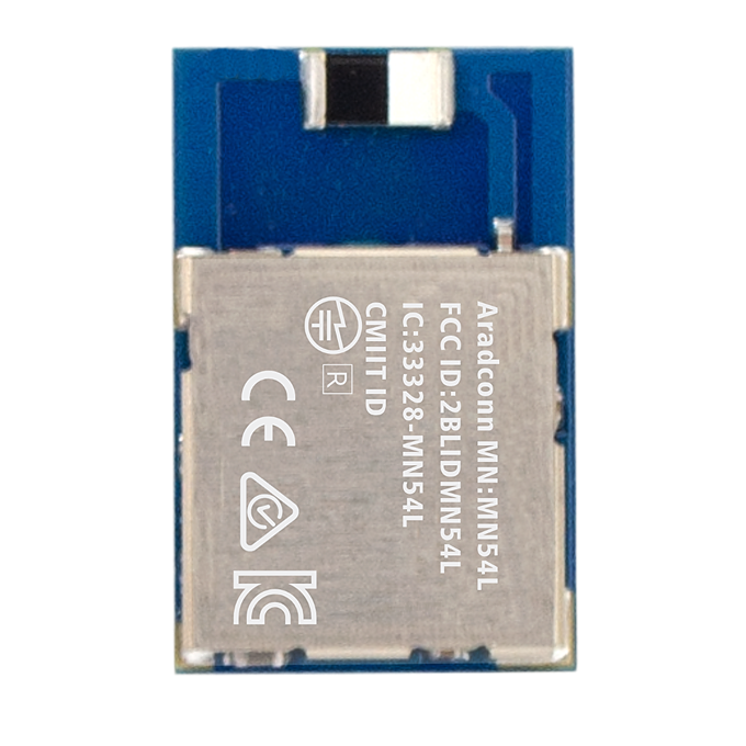
(LE Coded1M Field Test) From the data, a truth emerges: The MN54L-C15 Chip Antenna's communication distance increases by 22% when oriented correctly! Arad MN54L (Nordic nRF54L15 module) Transmission Range Takes a Leap Forward
Arad Connectivity MN54L (Nordic nRF54L15 module) Bluetooth Module open field range test Part 2.
[TAIWAN, 29th Aug. 2025]

This article shares the results of our open-field communication range test for the MN54L BLE module. The objective was to verify the difference in effective communication distance when the module is rotated by 90 degrees compared to its original orientation. The test compared the transmission performance of different antenna types (Chip and PCB) in various orientations. We used an iPhone 7 as the receiving device and conducted the tests in an open and unobstructed outdoor environment to simulate real-world application scenarios.
1. Test Objectives
- Verification of Communication Range Differences for MN54L BLE Modules in Original vs. 90-Degree Rotated Orientations in an Open-Field Environment
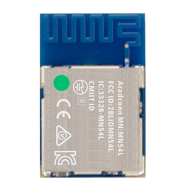
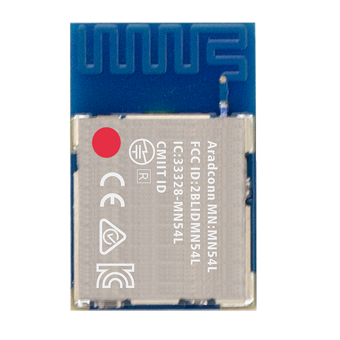
 Original Orientation
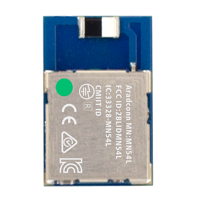
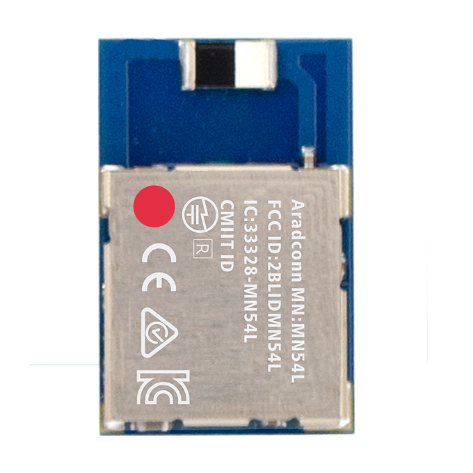
 90-Degree Rotated Orientation
- Compare communication performance among different antenna types (CHIP / PCB).
2. Test Environment
Outdoor Environment:
- Open and unobstructed area (Line-of-sight)
3. Equipment Required
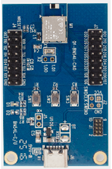
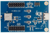
- BLE Signal Transmitting Device (Emitting Board)
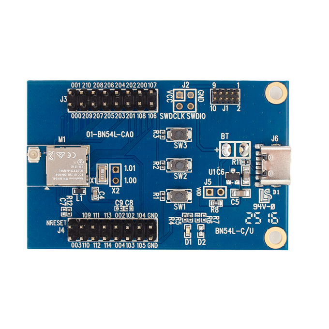
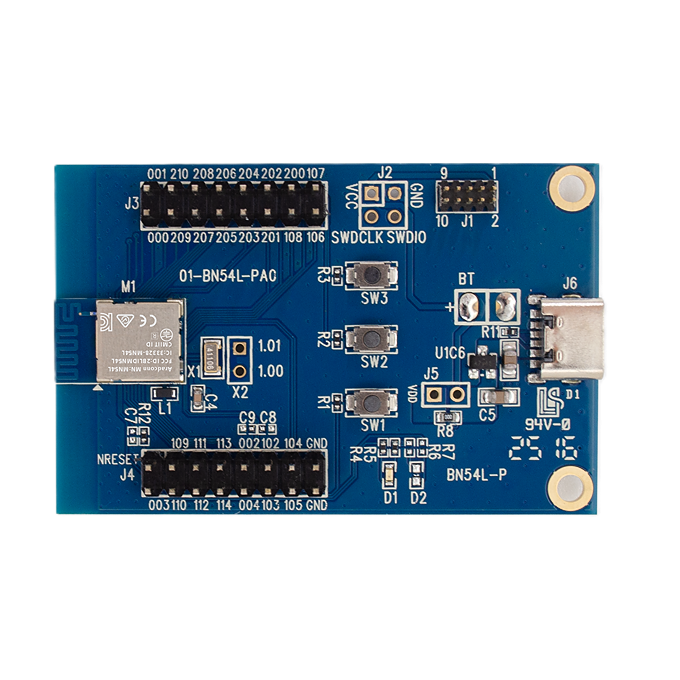
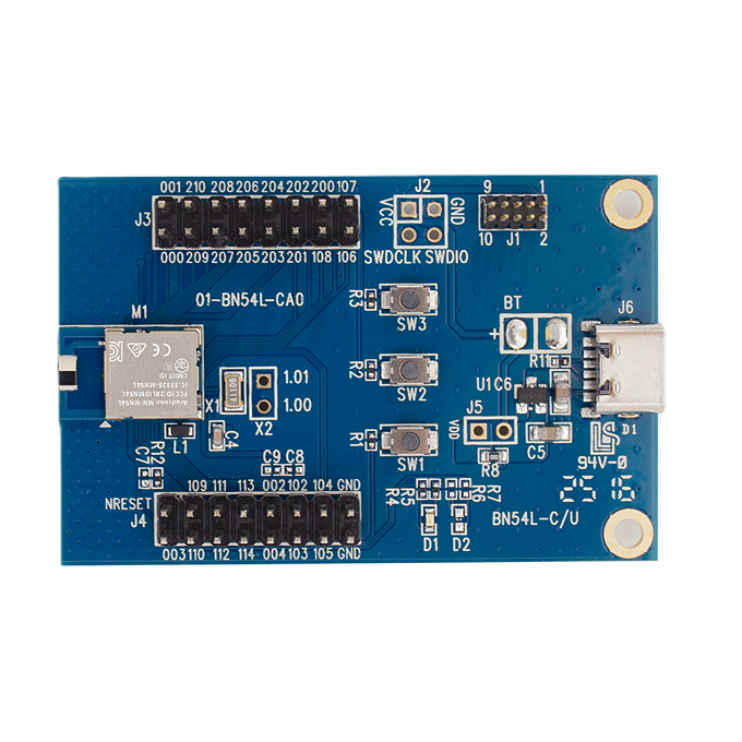
- Test Modules: MN54L-C15, MN54L-P15, MN54L-U15
- BLE Signal Receiving Device
- Test Device: iPhone 7
- Testing Software: LightBlue®

- Distance Measurement & Logging Tools: Google Maps, smartphone GPS positioning
4. Test Parameters
|
Parameter |
Description |
|
TX Power |
+8 dBm |
|
PHY Mode |
1M |
|
Packet Size |
20 bytes |
|
Direction |
Line-of-sight (LOS) |
|
Antenna Height |
3 meters above ground |
|
Transmission Mode |
Connection mode |
|
Environmental Conditions |
Temperature: 33°C, Humidity: 68% |
5. Test Procedure
- Establish a stable BLE connection between the iPhone 7 and the transmitting module, and confirm packet reception. (Confirm data linked.)
- Record transmission success rate at the starting point.
- Stay at each distance point for at least 10 seconds and log connection quality.
- Test the impact of different transmission angles on range performance.
- Conduct at least three test runs to verify consistency.
- Record the disconnection distance and the surrounding environmental conditions when the connection drops.
6. Test Records / Results
- Maximum distance comparison under different transmission angles
- Performance comparison table for each antenna type
- Device version and firmware information used in testing
- Anomaly logs (e.g., packet loss incidents)
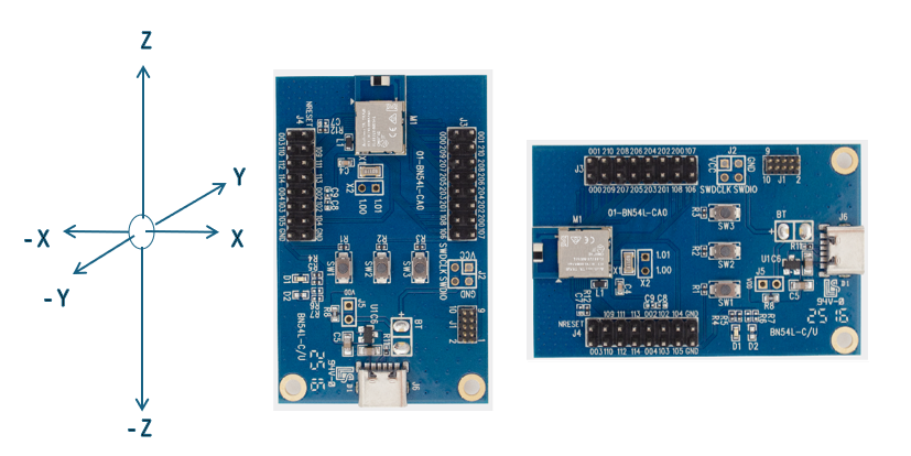
**************************************************Antenna Axis Defined**************************************************
*****************************************************************************************************************************
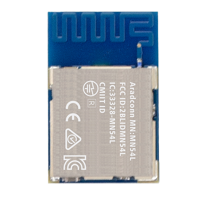
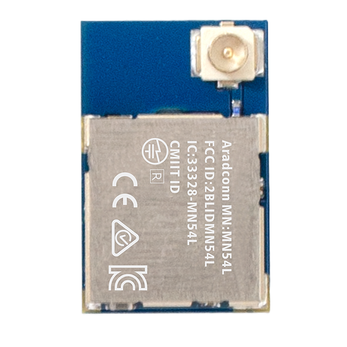
BN54L Series
Chip ANT (MN54L-C15)
Y, -Y: 540, 549 meters
R90°Y, R90°-Y: 648, 667 meters
PCB ANT(MN54L-P15)
Y, -Y: 577, 580 meters
R90°Y, R90°-Y: 458, 461 meters

1. Chip Antenna (MN54L-C15) Performance:
- Orientation-Insensitive Improvement: The transmission distance of the Chip Antenna in its original orientation (Y, -Y directions) was measured at 540-549 meters. After a 90-degree rotation (R90°Y, R90°-Y directions), the distance increased significantly to 648-667 meters. This indicates that for the Chip Antenna, a 90-degree rotation is beneficial for signal transmission, substantially boosting the communication range by approximately 20-22%.
- Optimized Placement: The test results strongly suggest that when using the MN54L-C15 Chip Antenna, its radio wave radiation characteristics in different orientations should be considered. It should be installed in a specific direction that maximizes the transmission distance to achieve optimal performance.
2. PCB Antenna (MN54L-P15) Performance:
- Orientation-Sensitive: The transmission distance of the PCB Antenna in its original orientation (Y, -Y directions) was excellent, at 577-580 meters. However, when the module was rotated by 90 degrees (R90°Y, R90°-Y directions), the transmission distance dropped sharply to 458-461 meters. This demonstrates that the PCB Antenna's performance is highly sensitive to the module's orientation, with a range reduction of about 20% after a 90-degree rotation.
- Optimal Direction is Key: The PCB Antenna has a clear optimal transmission direction. To ensure the longest possible communication range, the MN54L-P15 module must be designed and installed in strict adherence to its best antenna radiation pattern.
3. Comparison of the Two Antenna Types:
- Original Orientation: In its original orientation, the PCB Antenna (577-580 m) slightly outperformed the Chip Antenna (540-549 m) in transmission distance.
- Optimized Performance: After directional optimization, the Chip Antenna (648-667 m) surpassed the PCB Antenna's performance in its original orientation and performed far better than the PCB Antenna in its 90-degree rotated state.
In conclusion, the physical orientation of the antenna has a decisive impact on the Bluetooth module's transmission distance.
- If the design requires maximizing the transmission range, the MN54L-C15 Chip Antenna, when directionally optimized, can achieve the best long-distance transmission results.
- If using the MN54L-P15 PCB Antenna, the placement orientation must be considered very carefully to avoid a significant drop in performance due to an improper direction.
Edited by Intl. Commercial Development Manager: Mr. Tim Chien