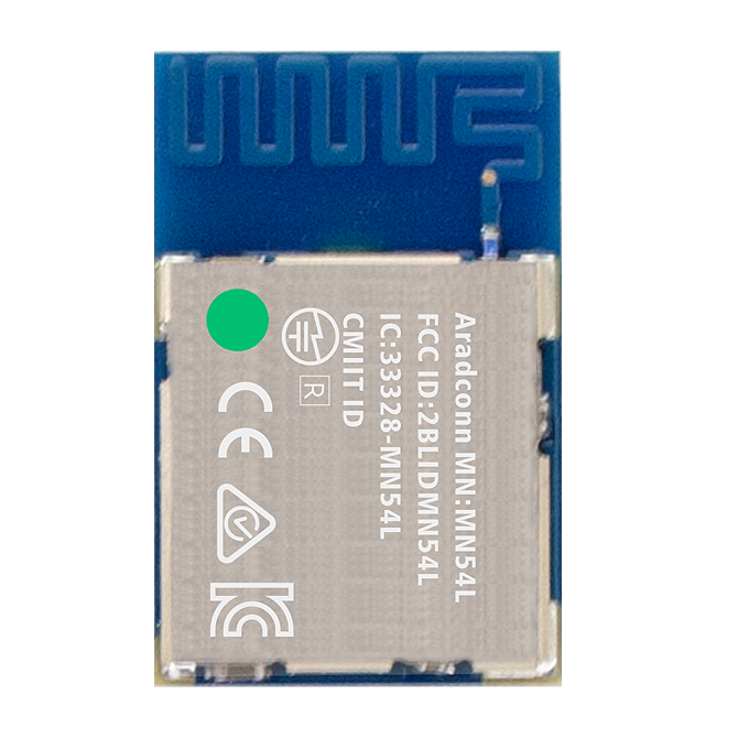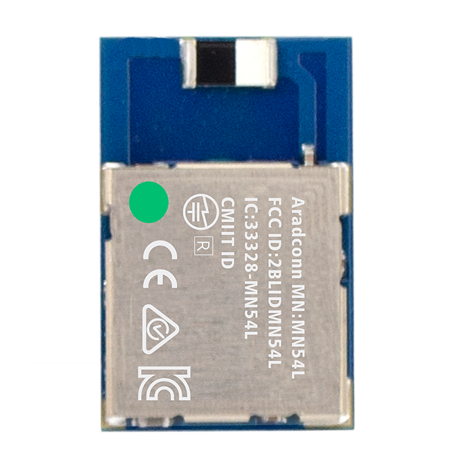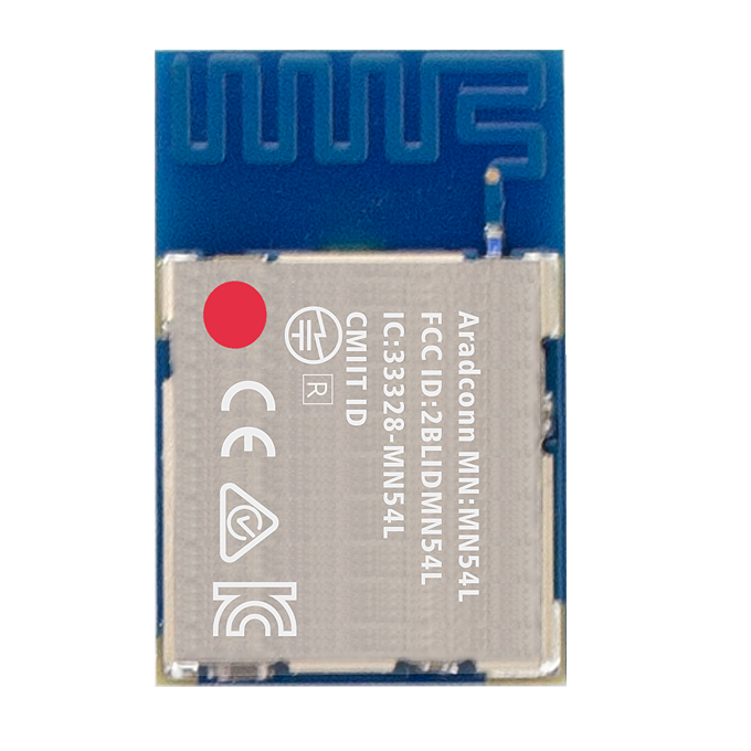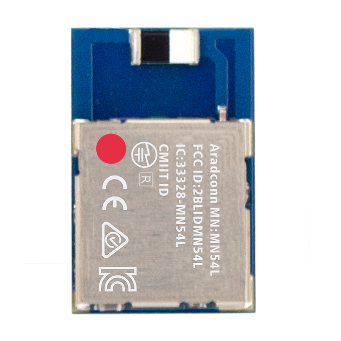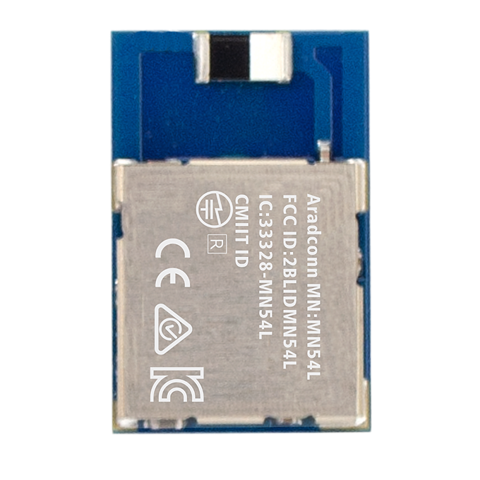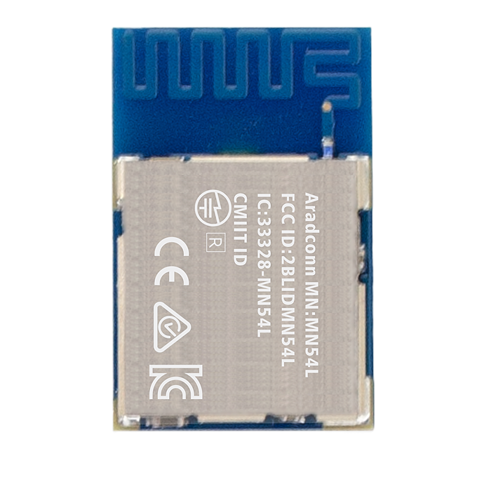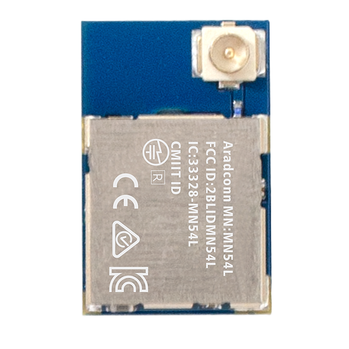

MN54L (nRF54L-15) Bluetooth Module Cycling Group Fall Behind Monitoring Test Report (1M & 125K PHY)
[TAIWAN, 09th September 2026]
[中文報告]
Introduction
With the growing popularity of recreational cycling and group riding activities, "group fall-behind” caused by differences in riding speed, traffic light intervals, or corner obstructions has become increasingly common. To provide cycling teams with real-time, highly reliable safety protection and separation alerts, Arad Connectivity has designed a BLE-based group monitoring mechanism tailored for cycling scenarios.
This test evaluates the RF penetration and transmission range performance of Arad Connectivity's MN54L series Bluetooth modules (based on the Nordic nRF54L platform architecture) in real-world riding environments. By comparing two physical layer protocols—1Mbps (Standard Mode) and 125kbps (Bluetooth Long Range / Coded PHY Mode)—we verify connection stability when facing complex obstacles such as buildings and road corners, establishing a baseline for group fall-behind algorithms and mass production configurations.
1. Test Objectives
✅ Measure Effective Communication Range: Verify the maximum stable connection range of Arad Connectivity's MN54L series modules in real urban obstructed environments.
✅ Compare PHY Mode Penetration Performance: Evaluate signal attenuation resistance between 1Mbps (Standard Mode) and 125kbps (Coded PHY Mode) in Non-Line-of-Sight (NLOS) environments with building obstructions and corners.
✅ Validate Alarm Mechanism & Hardware Integration: Test the real-time alarm trigger performance of the lead bike's (Master) integrated buzzer during signal threshold drops or disconnections.
2. Test Date & Environment
|
Item |
Details |
|
Test Date |
September 09, 2026 |
|
Test Environment |
New Taipei City Library Shulin Ganyuan Branch and surrounding areas. |
3. Equipment Required
|
Category |
Device |
Details |
|
Lead Bike (MASTER/CENTRAL) |
Arad Connectivity MN54L-U15 Module (nRF54L-15) & External Antenna ANTX100ETHAB24553 |
Integrated buzzer alarm mechanism, Tx Power: +8 dBm |
|
Follower Bike (SLAVE/PERIPHERAL) |
Arad Connectivity MN54L-C15 Module (nRF54L-15) |
Tx Power: +8 dBm |
|
Test Software |
Arad Connectivity Customized BLE Firmware |
Based on Nordic UART Service SDK |
|
Installation Location |
Placed in YouBike front baskets |
No metal or frame enclosure blockages |
|
Distance Measurement Tool |
Google Maps, Smartphone GPS Positioning |
|
|
Bicycles |
YouBike |
|
4. Test Parameters
|
Parameter |
Description |
|
TX Power |
+8 dBm (configured on MN54L-C15 module) |
|
PHY Mode |
125K (Long Range Mode); 1M (Standard BLE Mode) |
|
Packet Size |
20 bytes; 4 packets per second |
|
Direction |
1. Line-of-Sight (LOS): Open road with completely unobstructed line-of-sight. 2. Free Riding (NLOS): Real riding scenario with route corners, roadside buildings, and corner obstructions. |
|
Antenna Height |
3 meters above ground level |
|
Transmission Mode |
Connected Mode (Verifies valid packet transmission; at least 1 packet received. Buzzer alarm triggers after 10 seconds of zero packet reception). |
|
Environmental |
Temperature: 28°C, Humidity: 69%. |
5. Test Procedure
5.1 Equipment Deployment & Connection Calibration
1. Secure the MN54L-U15 (Master) and MN54L-C15 (Slave) into the front baskets of two YouBikes.
2. Power on the devices, confirm BLE connection establishment, and verify the buzzer alarm mechanism enters standby mode.
5.2 Line-of-Sight (LOS) Maximum Distance Test
1. Separate both bikes on the open road outside Ganyuan Library with clear line-of-sight. Measure and record the maximum physical distance while maintaining a stable connection without packet loss under 1Mbps and 125kbps modes.
5.3 Non-Line-of-Sight (NLOS) Dynamic Penetration Test
1. Riders ride freely along the streets surrounding the library, simulating real group riding scenarios with increased gaps, corner turns, and building obstructions.
2. Record the critical distance points where signal disconnection or group fall behind alerts are triggered.
5.4 Disconnection Alarm & Reconnection Response Test
1. Observe the trigger delay of the MN54L-U15 buzzer when exceeding maximum distance or encountering severe obstruction disconnections.
2. Record the auto-reconnection response speed upon returning to communication range.
6. Measurement Results
6.1 Equipment Deployment & Connection Calibration
|
Physical Layer (PHY) |
LOS Connected Distance |
Free Riding (NLOS with Corners/Buildings) |
Performance Gain |
|
1 Mbps (Default Mode) |
>300m |
80m |
Baseline |
|
125 kbps (Coded PHY) |
>300m |
168m |
+110% Range Increase |
6.2 Detailed Field Performance & Connection Quality
1. Line-of-Sight Field (LOS):
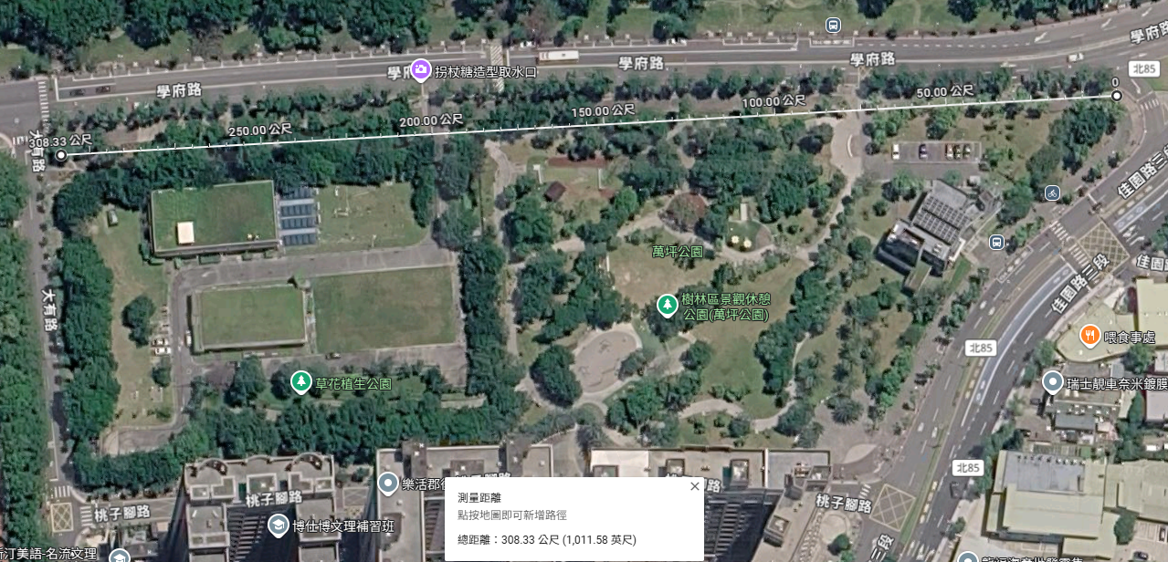
l In both 1M and 125kbps modes, Packet Delivery Ratio (PDR) remained high at 300 meters, with zero false buzzer triggers. Due to physical road length constraints, actual potential range exceeds 300m.
PHY 1M LOS test
2. Urban Non-Line-of-Sight Field (NLOS):
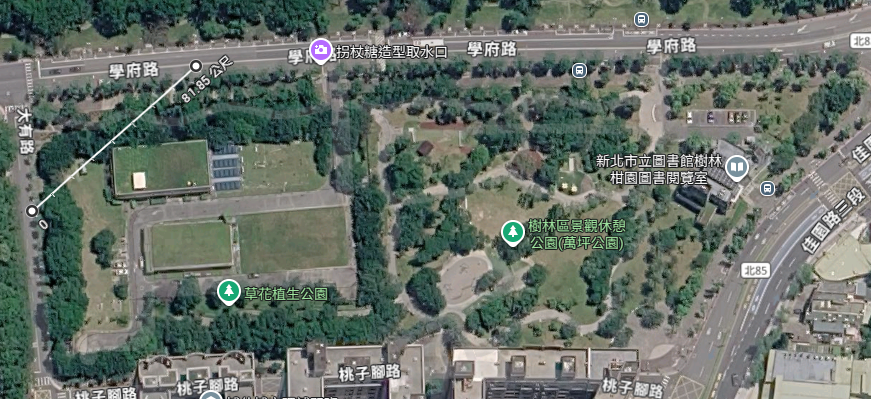
l 1Mbps Mode: As bikes turned corners into building blind spots around 80 meters, signal experienced severe attenuation triggering disconnection. The buzzer issued an immediate fall behind alarm within 2 seconds.
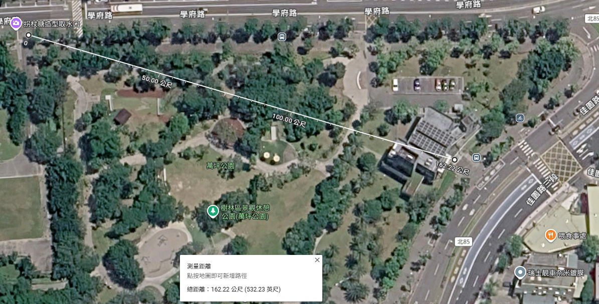
l 125kbps (Coded PHY) Mode: Demonstrating superior RF link margin, connection successfully extended to 168 meters around identical corners, significantly delaying false alarms from temporary blind spots. Disconnection occurred only when blocked by large structures like the main library building.
PHY 1M NLOS test
PHY 125kbps NLOS test
Test Conclusions & Product Application Recommendations
1. Exceptional RF Performance (Open Field):
l In unobstructed (LOS) environments, the MN54L series modules maintained stable connections beyond 300 meters in both 1Mbps and 125kbps modes, proving excellent antenna matching and RF output quality capable of covering long-distance group monitoring requirements.
2. Coded PHY Demonstrates Strong Obstruction & Multipath Resistance:
l In real free-riding (NLOS) tests featuring trees, corners, and building blockages, switching to 125kbps (Coded PHY) expanded effective connection range from 80 meters to 168 meters (+110% gain). This confirms Coded PHY effectively compensates for signal attenuation and multipath interference in urban environments.
3. Adaptive PHY Firmware Optimization Recommendations:
l Cruising Phase: Default to 1Mbps mode during normal riding to leverage higher data update rates and lower power consumption for dynamic RSSI sampling.
l Blind Spot & Fall Behind Warning Phase: When the system detects rapid RSSI drops or blocked line-of-sight around corners, firmware should automatically trigger adaptive switching to 125kbps mode. This prevents false alarms caused by temporary building obstructions while maintaining a robust group connection.
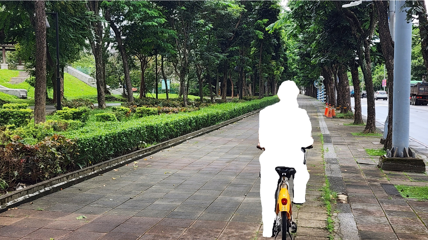
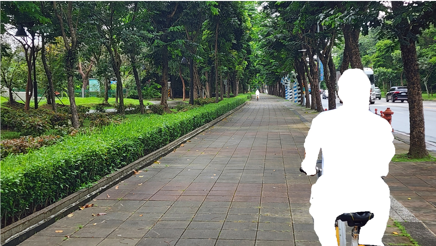
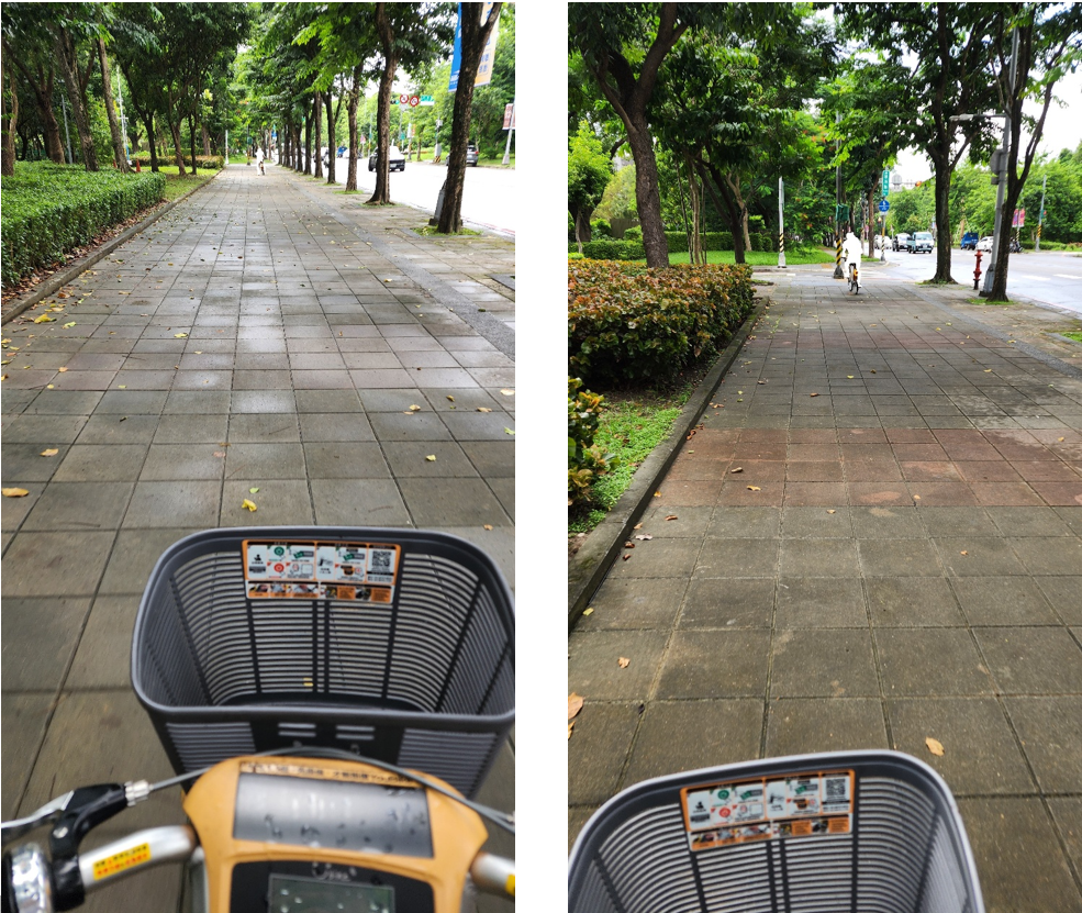
Image and Text Copyright Statement:
All text and image content in this article (including but not limited to headings, body text, analysis, and summaries) are the copyright of Arad Connectivity Co., Ltd. Any form of reproduction, reprinting, modification, or commercial use without written authorization is strictly prohibited.
📢 Get Ready for Our Latest Episode of BLE Tech Pulse Decoded on Aradtube!
We're diving deeper into this fascinating topic! Subscribe to our channel and hit that notification bell so you don't miss our latest video releases.
🔗 YouTube: https://www.youtube.com/@Aradconn
Edited by Intl. Commercial Development Manager: Mr. Tim Chien