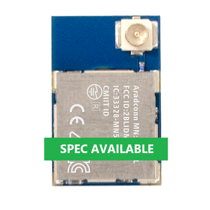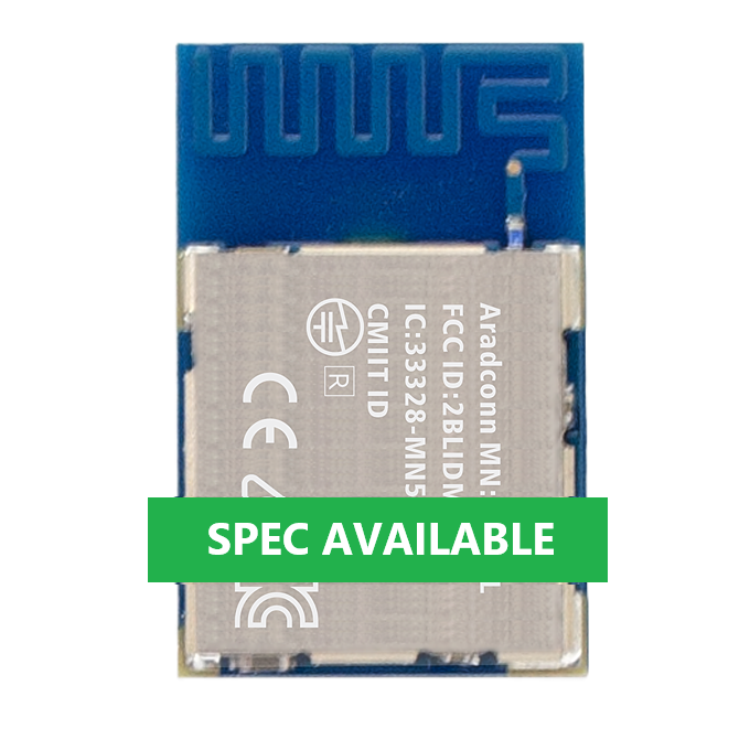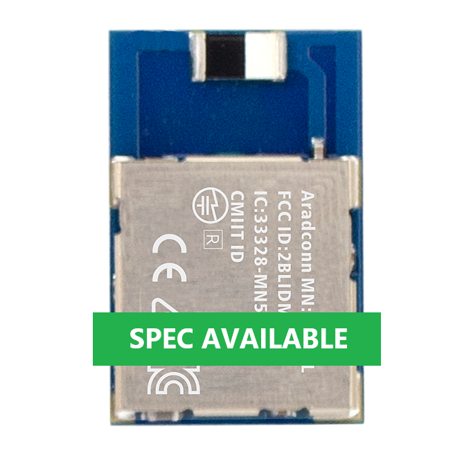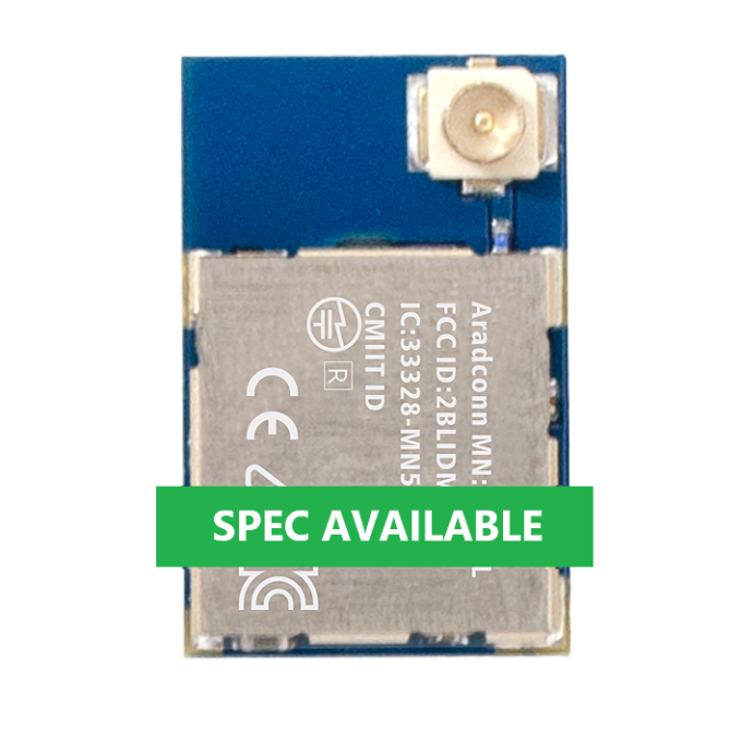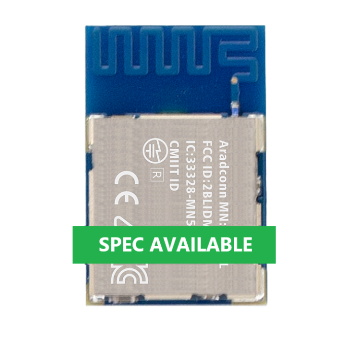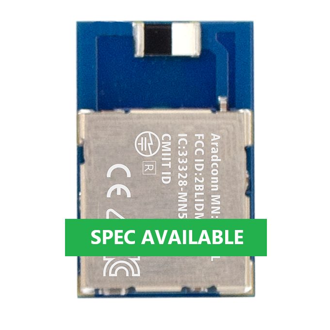

Arad Connectivity MN54LM-20A (nRF54LM-20A) BLE Module Module-to-Module Full-Axis Test Report (1M & 125K PHY)
[TAIWAN, 04th August 2026]

[中文版報告]
[Module to Smartphone test report]
Introduction
Conducted in the open outdoor environment of the Zhuwei seaside, this test aims to thoroughly investigate the actual impact of module miniaturization on effective wireless connection ranges. This evaluation comprehensively assesses the Arad Connectivity MN54LM-20A series BLE modules (nRF54LM-20A)—featuring built-in CHIP, PCB antennas, and external u.FL antenna versions, excluding the S20A model. Shifting from previous smartphone-to-module setups to a module-to-module bi-directional connection architecture, the testing scope simultaneously incorporates both standard 1M PHY and long-range 125K PHY transmission modes to comprehensively verify the extreme communication performance and multi-axis propagation characteristics in a coastal environment.
1. Test Objectives
✅ To completely verify the effective communication distance of the Arad Connectivity MN54LM-20A series BLE modules in bi-directional communication (MASTER/CENTRAL to SLAVE/PERIPHERAL) in an open field.
✅ To test the communication performance across all axes for modules equipped with built-in CHIP, PCB antennas, and external u.FL antenna versions.
2. Test Date & Environment
|
Item |
Details |
|
Test Date |
July 30, 2026 |
|
Test Environment |
Outdoor environment, Zhuwei Bathing Beach, Taoyuan City. |
3. Equipment Required
|
Category |
Device |
Details |
|
SLAVE/PERIPHERAL |
Emitting Board (DUT) |
MN54LM-C20A, MN54LM-P20A, MN54LM-U20A Modules (nRF54LM-20A) |
|
MASTER/CENTRAL 1 |
MN52H-U40 |
Transmit Power (Tx Power): 8 dBm |
|
External Antenna Types |
||
|
Test Software |
LightBlue®; Aradconn custom BLE firmware. (Based on Nordic UART Service SDK.) |
|
|
Measurement Tools |
Google Maps, Mobile GPS Positioning. |
4. Test Parameters
|
Parameter |
Description |
|
TX Power |
+8 dBm (Set on MN54LM-20A series and MN52H-U40 modules) |
|
PHY Mode |
125K (Long Range Mode); 1M (Standard BLE Mode) |
|
Packet Size |
20 bytes; 4 packets per second |
|
Direction |
Line-of-Sight (LOS) path maintained for distance measurement. |
|
Antenna Height |
3 meters above ground level |
|
Transmission Mode |
Connected mode (Verifying valid packet transmission, receiving at least one packet set). |
|
Environmental |
Temperature: 32.5°C, Humidity: 75%. |
5. Test Procedure
This procedure aims to measure the maximum transmission distance of the MN54LM-20A series Bluetooth modules under different antenna configurations in standardized and repeatable conditions.
5.1 Preparation and Connection Establishment
1. Equipment Setup: Establish an active connection between the MN52H-U40 EVB and SLAVE devices (MN54LM-C20A, MN54LM-P20A, MN54LM-U20A), and verify packet reception.
2. Transmission Rate: Set to 125K or 1M mode, transmitting 4 packets per second.
3. Starting Point Positioning: Fix the SLAVE device at the starting point, 3 meters above the ground, ensuring all antenna directions face the intended movement path.
4. Connection Check: The MASTER device establishes an active connection with the SLAVE device at the starting point and performs bi-directional packet transmission. Packet reception status is displayed and confirmed via flashing indicator lights on the module.
5.2 Distance Measurement and Data Logging
1. Incremental Test: The MASTER device (MN52H-U40 EVB) moves outward along the line-of-sight distance path in 10-meter increments.
2. Stop and Monitor: At each measurement point, verify the connection status of the MASTER device and continue moving outward.
3. Limit Distance Determination: Continue moving until the connection can no longer be stably maintained (e.g., success rate remains persistently low or connection completely drops, at which point indicator lights stop flashing). Use Google Maps and GPS positioning tools to precisely record the disconnection distance and environmental characteristics at the time of disconnection.
6. Test Records (Maximum Effective Connection Distance)
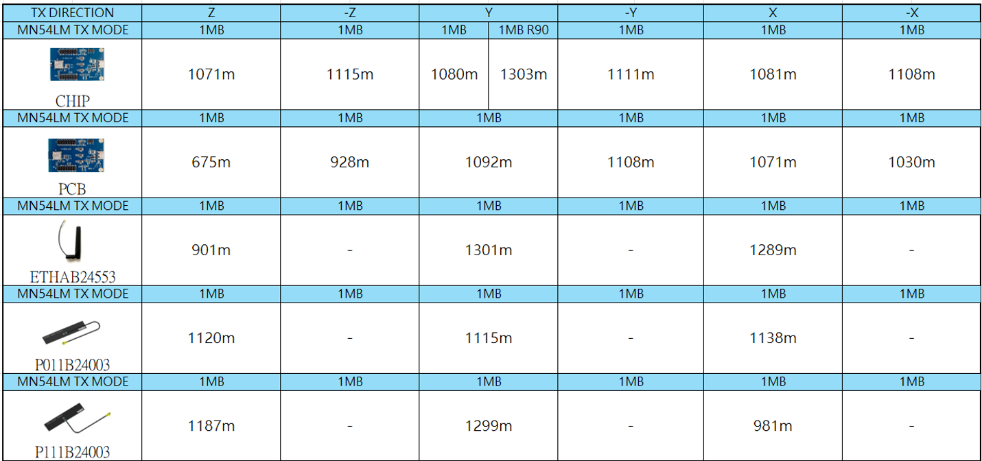
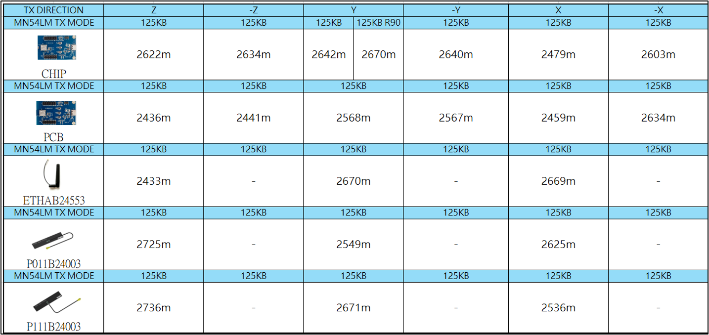
The table below shows the maximum effective distance at which the MN54LM-20A series modules maintained a stable bidirectional connection and received at least one packet over long ranges:
PHY 1M
PHY 125K
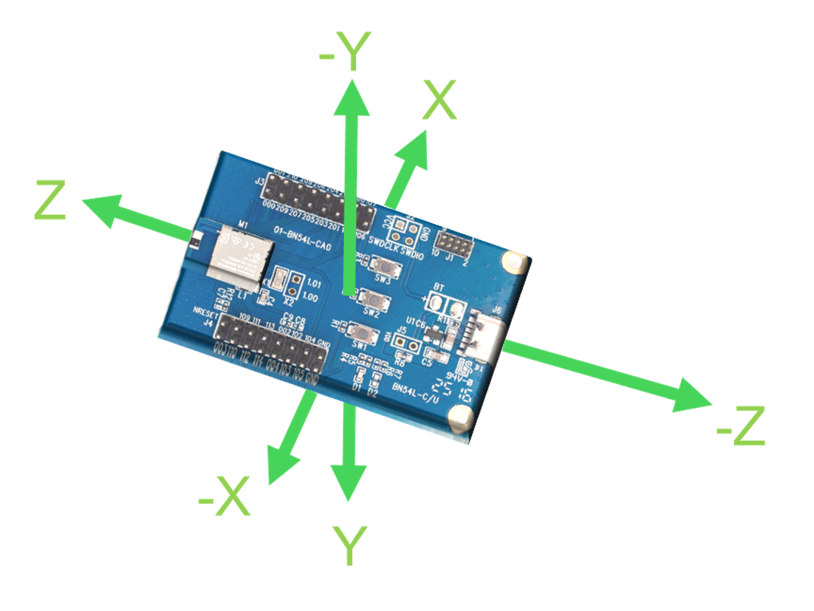
MN54LM-C20A/P20A/U20A Maximum Range Positioning Map (All Axes) PHY︰1M
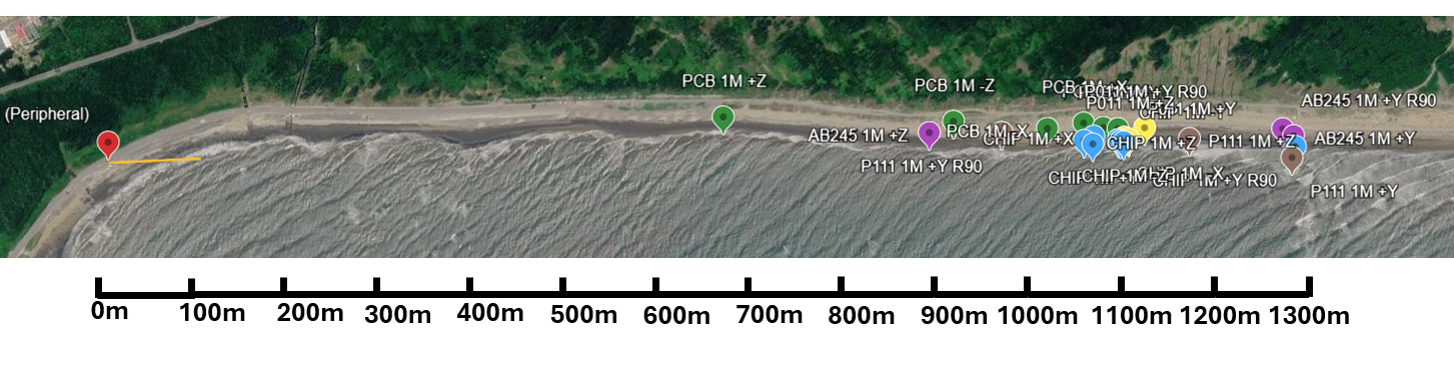
Note: The aerial view is not a photo of the actual site.
MN54LM-C20A/P20A/U20A Maximum Range Positioning Map (All Axes) PHY︰125K
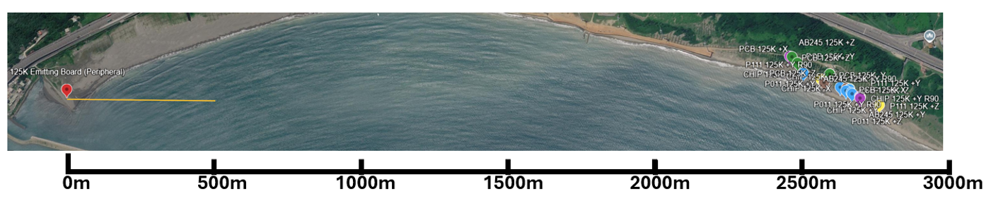
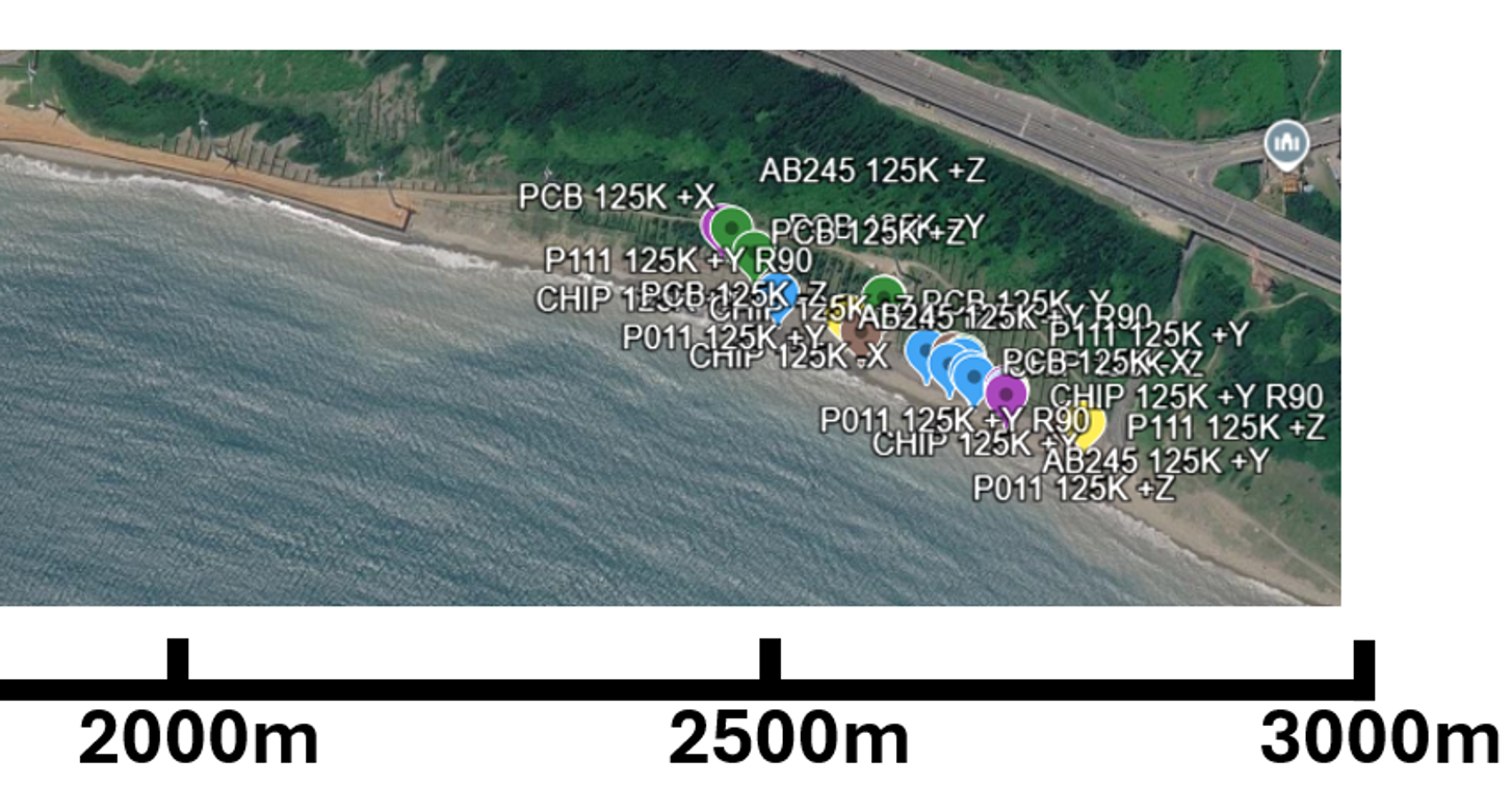
Note: The aerial view is not a photo of the actual site.
Test Conclusions
Based on the module-to-module field test data obtained at the Zhuwei seaside (covering both 1M PHY and 125K PHY modes), the performance of the Arad Connectivity MN54LM-20A series modules can be summarized by the following key conclusions:
Breakthrough Range Enhancement via PHY Modes:
Under the 1M PHY standard mode, the effective communication distance for various antenna versions generally ranges between 675 meters and 1187 meters (e.g., the PCB antenna reaches 675m on the Z-axis, while the external P111B24003 antenna reaches 1187m on the Z-axis).
Upon switching to 125K PHY (Long Range mode), benefiting from coding gain, transmission distances increase exponentially, breaking through the 2.4 km to 2.7 km threshold. Notably, the external P111B24003 antenna achieved a maximum extreme distance of 2736 meters on the Z-axis, while the CHIP antenna reached 2670 meters after Y-axis rotation (R90).
Full-Axis Performance and Rotational Optimization of Built-in Antennas (CHIP and PCB):
The CHIP antenna demonstrated exceptional stability, maintaining around 1071m to 1115m across axes in 1M mode, with its Y-axis 90-degree rotation (R90) boosting the range from 1080m to 1303m; in 125K mode, it consistently maintained between 2479m and 2670m.
The PCB antenna performed strongly on the -Y and X axes in 1M mode (exceeding 1070m), though lower on the Z-axis (675m), indicating stronger directivity. In 125K mode, it showed excellent equilibrium, sustaining 2436m to 2634m across all axes.
Extreme Performance of External u.FL Antenna Versions:
Pairing with external antennas (such as ETHAB24553, P011B24003, and P111B24003) effectively pushes transmission limits along specific axes. For instance, the external P111B24003 antenna achieved 1187m on the Z-axis in 1M mode and 2736m in 125K mode, proving that external antenna solutions provide high flexibility and stability for long-range applications.
Image and Text Copyright Statement:
All text and image content in this article (including but not limited to headings, body text, analysis, and summaries) are the copyright of Arad Connectivity Co., Ltd. Any form of reproduction, reprinting, modification, or commercial use without written authorization is strictly prohibited.
📢 Get Ready for Our Latest Episode of BLE Tech Pulse Decoded on Aradtube!
We're diving deeper into this fascinating topic! Subscribe to our channel and hit that notification bell so you don't miss our latest video releases.
🔗 YouTube: https://www.youtube.com/@Aradconn
Edited by Intl. Commercial Development Manager: Mr. Tim Chien